

Boltorr Road Halt
Well, let’s get straight to the point. There’s been a bit of a break caused mostly by my right arm being in plaster or otherwise immobile for a month or so. But the time did enable me to take a pause for thought.
A 12ft x 2ft format turned out to be a feasible, but tight squeeze and really a bit unmanageable in the space I have. The layout will be housed in our cellar, a luxury for most UK modellers I know, but this one is subdivided in a way not ideal from the railway layout point of view. I know, first world problems. So I decided to cut the layout to 8ft x 2ft, having already assembled three 4ft modules. This leaves plenty of room for a fiddle yard at either end.
It’s not such a big deal. It’s my first real model, after all, and leaves room for my next project … more about that when Boltorr Road is well under way.
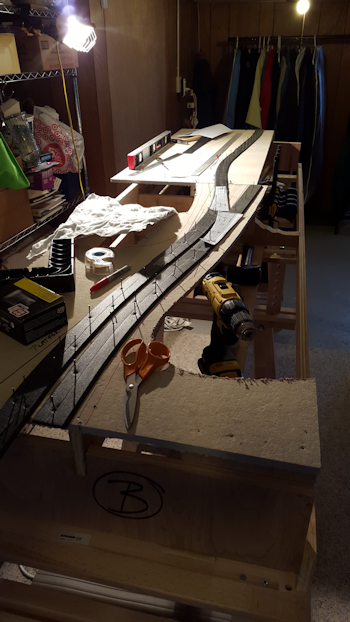
Laying the track foundation at Boltorr Rd – from the north
I was originally intending to keep the modules metric. But this is the US and frankly, I could not face the prospect of cutting every piece individually. As it is, I found a lumber merchant who was helpful enough to reduce an 8ft x 4ft x 18mm plywood board to a collection of useful pieces which could be joined in several ways to cope with the topography of the scene I have in mind.
So my first job has been to establish a level track plane while the landscape rises and falls around it.
The track support surface itself is cut from a light fibre board sold as Homasote here. It seems very similar, if not identical to SunDeala board as sold in the UK. Although the foundation is trimmed to within an inch or so of the track, the bed itself is supported by plywood beams. This makes for a sturdy, stable, but fairly lightweight and open support.
I used a spirit-level to true up the baseboard module and temporarily tacked the large Homasote boards while I determined the layout of the track. I wanted to convey the idea of smooth sweeping curves. My fixed points were a crossover determined by turnout geometry and a bridge over a small river.
I first determined the curves using pins and a 4ft steel rule. My first job was as a technician shipwright apprentice who went on to work in a ships’ drawing office, so I have a good eye for developing transition curves. The ruling curve radius is about 6ft, although the points are about 60 inches with the curved point turn out being less than that.
The tightest curve is on the exit from what will be a bridge over a stream. I’ll probably fit a check-rail at that point.
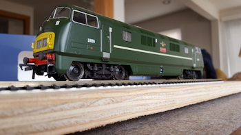
D835 “Pegasus” awaiting detailing, dirtying and digitalising
Prototypically that means a radius of 7 chains, tight, but I don’t think unfeasible on a branchline running through rolling countryside, and still large enough to accommodate a mainline engine with a sensible speed limit.
The aim is that the curves and transitions look smooth and authentic and I hope will be a big contribution to the layout’s atmosphere.
My first attempt needed adjusting when I found one of the points was situated right over a plywood support which meant I couldn’t fit a sub-baseboard point motor. So there was a bit of re-alignment to accommodate this.
After determining the line, I trimmed the Homasote. This material is easy to cut, but produces a filthy dust. Fortunately, I’d been warned about this so cut it outside. It was then pinned and glued onto the sub-frame with a final check for level and true.
Which is basically where I am now. Next job is to cut the void for the bridge, fix the points and figure out how to switch them with DCC. Once the actual track is fixed then I’ll figure out the lie of the land.
Next article: Boltorr Road Halt. A short history …