
The major difference from the time of my first faltering steps in railway modelling has been the introduction of DCC – Digital Command Control.
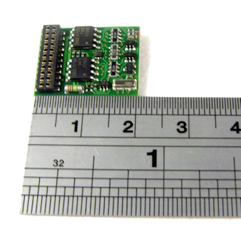
A DCC decoder chip usually fitted inside the model locomotive
There are a number of issues with 2-rail. Firstly, all the locomotives on the layout potentially receive the same feed so if you want just one to move, or move more independently you have to be able to isolate sections the track so that your feed only reaches the locomotive you want to control. There are also issues with feeds through points/switches and if you want to have a reverse loop or triangle on your line. But, of course, visually it is the most realistic.
In practice though, it meant that any model railway which constituted much more than a circle and a siding required sectioning and switching in a manner very similar to a real railway, so there was much to be said for it.
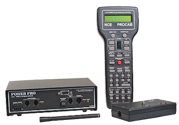
Boltorr Rd’s NCE Power Pro / ProCab r combination
In a nutshell, the entire track-work on the layout receives a constant AC supply, generally around 16v, over which digital signals are overlaid and then sensed and interpreted by a decoder circuit installed in each engine. Each chip is allocated a unique address number and only acts on commands transmitted to that address from the handset, or cab. Decoder equipped Cobalt IP Digital points motors can also be controlled from the cab. The cab also supports macros and consists – running two or more locomotives together as a single unit. There is still a need for some current switching at pointwork, and loops still require a polarity switch, although this can be automated in DCC.
Below is a schematic for Boltorr Road showing the basic connections.
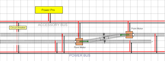
The system is divided into two linked regions, the power bus feeds the locomotives and the accessory bus the points motors. There is a circuit breaker to protect against short circuits and overloads
Next jobs; fit decoder chips to locomotives and programme the crossover motors so they digitally interlock; start on terraforming landscape